
- 非IC关键词
企业档案
- 相关证件:

- 会员类型:普通会员
- 白卫平

- 电话:029-88221540
- 手机:13720772046
- 地址:西安市雁塔区太白南路263号
- 传真:029-88221540
- E-mail:baiweiping@365-24.com.cn
产品分类
您的当前位置:上海集新电子通讯器材有限公司 > 元器件产品
相关产品

产品信息
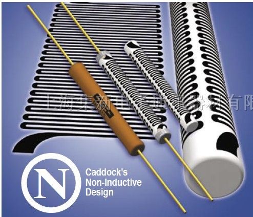
Power Film Resistor Family with Wide Resistance Range and +275°C Maximum Temperature
With power ratings to 22 Watts and voltage ratings as
high as 6,000 volts in an axial-lead resistor with values to
30 Megohms, the T*e MS Power Film Resistors deliver
the performance capabilities that can simplify circuit
design and reduce equipment cost and complexity.
T*e MS Power Film Resistors provide all these features in
a single resistor:
• Full power and voltage ratings, without derating:
- for non-inductive performance.
- for high resistance values that extend the critical
resistance value up to 10 times.
• Higher voltage ratings without the limitations of minimum
wire size and spacing.
• Excellent long-term stability.
Tests demonstrate t*ical stability of 0.05% per 1,000
hours over extended life.
Micronox® Resistance Films
T*e MS performance begins with Caddock's Micronox®
resistance films. Produced exclusively by Caddock
Electronics, these proven complex oxide fi lms have been
used reliably for over 30 years in Caddock's precision power
resistor products.
Micronox® resistance films are fired directly onto a
ceramic core at temperatures above 1400°F (760°C). These
resistance films have demonstrated outstanding stability
when exposed to a high ambient temperature, thermal shock
and high power densities.
This unique approach to precision power resistors opens
new design possibilities by providing a wider resistance
range, precise temperature characteristics, and higher
temperature and power handling capability.
The Serpentine Pattern used in this patented product
contain features which enhance high stability in
High-Power Resistor applications.
Most models are manufactured with Caddock's
Non-Inductive serpentine resistive pattern that provides for
neighboring lines to carry current in opposite directions,
thereby achieving maximum cancellation of fl ux fi elds over
the entire length of the resistor. This effi cient non-inductive
construction is accomplished without derating of any
performance advantages.
The result is a truly non-inductive resistor that is about as
inductive as a straight piece of wire the length of the resistor
body. This effi cient design means faster settling times and
minimum distortion in all t*es of high frequency circuits.
Manufacturing Control
T*e MS Resistors are produced under intensive
manufacturing controls with processes which include power
conditioning, overvoltage conditioning, and maximum
temperature conditioning.
Quality Control
From the certifi cation and testing of all materials, to the
su per vi sion of manufacturing processes, all Caddock T*e
MS Power Film Resistors are produced under pro ce dures
that have been approved for conformance to the
requirements of Mil-I-45208 in many recent surveys as
described on page 8.
Reliability Verifi cation
T*e MS resistors are included in the Caddock Reliability
Testing Program. Conformance to specifi cation parameters
including Extended Life, Shock, Vibration, and Humidity are
verifi ed on a periodic basis. Data from T*e MS resistors
can be compared by similarity to other Caddock resistor
t*es, since T*e ML, MM, MS, MP, MG, and MK represent
an identical combination of materials - aluminum oxide
substrate, Micronox® resistance fi lm, and silicone insulating
coating.
Carefully Controlled Manufacturing and Test Procedures Assure Compliance with
Strict Quality Control Requirements.
N Caddock's
Non-Inductive
Design
T*e MS Power Film Resistors
Certain products shown in this catalog are covered by one or more patents, there are also patents pending.
CADDOCK
Specifi cations:
Resistance Tolerance: ±1% (tolerances to 0.1% on
special order).
Temperature Coeffi cient: 50 ppm/°C. TC referenced
to +25°C, ΔR taken at -15°C and +105°C.
Insulation Resistance: 10,000 Megohms, min.
Overload/Overvoltage: 5 times rated power with applied
voltage not to exceed 1.5 times maximum continuous operating
voltage for 5 seconds. ΔR 0.5% max. or 0.5 ohm
max., whichever is greater.
Thermal Shock: Mil-Std-202, Method 107, Cond. C, ΔR
0.5% max. or 0.5 ohm max., whichever is greater.
Moisture Resistance: Mil-Std-202, Method 106, ΔR 0.5%
max. or 0.5 ohm max., whichever is greater.
Load Life: 1,000 hours at rated power at +25°C or
+125°C (see derating curve), not to exceed rated voltage,
ΔR 0.5% max. or 0.5 ohm max., whichever is greater.
Maximum Operating Temperature: +275°C.
Encapsulation: High Temperature Silicone Conformal.
MS313, MS315
MS310
MS281
MS260
MS245
MS244
MS223
MS221
MS220
MS214
MS176, MS210
MS151, MS175
MS126, MS150
* Limited by power rating.
Models with Caddock's Non-Inductive Resistance Pattern are in non-shaded areas.
Models with low inductance construction are in shaded areas.
Ordering Information: MS220 -100K - 1%
Model Number:
Resistor Value:
Tolerance
RATED POWER OR
RATED VOLTAGE, %
A*ENT TEMPERATURE, °C
100
80
60
40
20
0
25
A B
A - all MS models
except MS126,
MS151, MS176
B - MS126, MS151,
MS176
Derating Curve:
1.500 ± .125
(38.10 ± 3.18)
A B C
DIMENSIONS IN INCH* AND (MILLIMETERS)
MS322
Dielect.
Strength
Model
No. C
Resistance Dimensions in inches and (millimeters)
Min. Max.
Max.
Voltage A B
.020 ±.002
(.51 ±.05)
.070 ±.015
(1.78 ±.38)
.188 ±.020
MS126 0.25 200 500 20 Ω 1 Meg (4.78 ±.51)
.020 ±.002
(.51 ±.05)
.070 ±.015
(1.78 ±.38)
.188 ±.020
MS150 0.50 500 20 Ω 2 K (4.78 ±.51)
.025 ±.002
(.64 ±.05)
.094 ±.015
(2.39 ±.38)
.250 ±.020
MS151 0.50 300 750 20 Ω 2 Meg (6.35 ±.51)
.025 ±.002
(.64 ±.05)
.094 ±.015
(2.39 ±.38)
.250 ±.020
MS175 0.75 750 20 Ω 2 K (6.35 ±.51)
.025 ±.002
(.64 ±.05)
.094 ±.015
(2.39 ±.38)
.313 ±.020
MS176 0.75 500 750 45 Ω 5 Meg (7.95 ±.51)
.025 ±.002
(.64 ±.05)
.094 ±.015
(2.39 ±.38)
.313 ±.020
MS210 1.0 750 45 Ω 3 K (7.95 ±.51)
.025 ±.002
(.64 ±.05)
.109 ±.025
(2.77 ±.64)
.313 ±.030
MS214 1.0 500 750 45 Ω 5 Meg (7.95 ±.76)
.025 ±.002
(.64 ±.05)
.140 ±.030
(3.56 ±.76)
.400 ±.060
MS220 2.0 Ω 10 Meg (10.16 ±1.52)
.032 ±.002
(.81 ±.05)
.165 ±.030
(4.19 ±.76)
.575 ±.050
MS221 3.0 Ω 10 Meg (14.61 ±1.27)
.040 ±.002
(1.02 ±.05)
.230 ±.030
(5.84 ±.76)
.480 ±.060
MS223 3.0 800 1,000 20 Ω 4 Meg (12.19 ±1.52)
.040 ±.002
(1.02 ±.05)
.230 ±.030
(5.84 ±.76)
.950 ±.060
MS244 4.0 2,000 1,000 45 Ω 15 Meg (24.13 ±1.52)
.040 ±.002
(1.02 ±.05)
.300 ±.030
(7.62 ±.76)
.570 ±.060
MS245 4.0 800 1,000 20 Ω 6 Meg (14.48 ±1.52)
.040 ±.002
(1.02 ±.05)
.300 ±.030
(7.62 ±.76)
.970 ±.060
MS260 6.0 2,000 1,000 45 Ω 15 Meg (24.64 ±1.52)
.040 ±.002
(1.02 ±.05)
.350 ±.040
(8.89 ±1.02)
.910 ±.060
MS281 8.0 2,000 1,000 45 Ω 8 Meg (23.11 ±1.52)
.040 ±.002
(1.02 ±.05)
.350 ±.040
(8.89 ±1.02)
1.250 ±.070
MS310 10.0 4,500 1,000 45 Ω 20 Meg (31.75 ±1.78)
.040 ±.002
(1.02 ±.05)
.350 ±.040
(8.89 ±1.02)
2.000 ±.080
MS313 12.5 6,000 1,000 50 Ω 30 Meg (50.80 ±2.03)
.040 ±.002
(1.02 ±.05)
.350 ±.040
(8.89 ±1.02)
2.000 ±.080
MS315 15.0 1,000 50 Ω 1 Meg (50.80 ±2.03)
*
*
*
*
Wattage
at
+125°C
Wattage
at
+25°C
0.25
0.50
0.75
0.30
0.45
0.60
0.60
1.2
1.8
1.8
2.4
2.4
3.6
4.8
6.0
7.5
9.0
.040 ±.002
(1.02 ±.05)
.350 ±.040
(8.89 ±1.02)
3.000 ±.090
MS322 22.0 13.2 * 1,000 100 Ω 1.5 Meg (76.20 ±2.29)
Construction:
The T*e MS Power
Film Resistor is constructed
with Micronox® resistance fi lms
bonded to a high strength solid
ceramic core. Nickel alloy end caps
and axial leads complete the *embly.
Encapsulation is provided by a high
temperature silicone conformal coating.
T*e MS: Lead material is Nickel Clad Copper
with thin Gold Plate, solderable.
For welding applications, optional pure nickel
leads are available on Models MS126, MS150,
MS151, MS175, MS176, MS210. Contact
Caddock Applications Engineering.
T*e MS Power Film Resistors
Page 2 of 2
28_IL108.1004